

Concentric/Eccentric Reducer
- Size Range: ½" NB to 24" NB in (DN6~DN100) 10s, Sch 40s, Schedule 80s, 160s, XXS.
- Dimensions: ANSI/ ASME B16.9, ASME B16.28, MSS-SP-43, BS4504, BS1560, BS4504, BS10
- Bending Radius: R= 1D, 8D, 2D, 5D, 3D, 6D, 10D or Custom Pipe Fittings
- Types: Seamless / Welded / ERW / Fabricated Pipe Fittings
- Introduction
- Feature
- Application
- Pictures
- Video
- Download
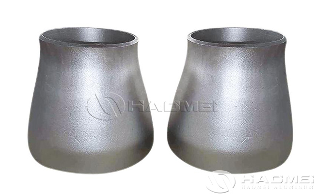
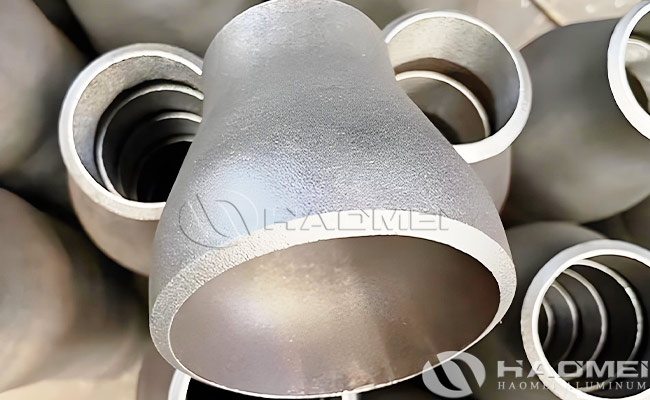
Aluminum reducers are aluminum pipe fittings used to connect two pipes of different diameters. They are usually made of aluminum because of its light weight, corrosion resistance, and low cost. Aluminum reducers can be concentric, meaning that their centerlines coincide with the centerline of the pipe, or eccentric, meaning that their centerlines do not coincide.
Concentric and eccentric reducers are maximum resistance to pressure, gradual change in pipe diameter and minor pressure drop. These reducer fittings are designed to be installed easily with optimal performance in different systems. They have been designed to work on high-pressure systems and other environmental challenges, giving more durable solutions.
The reducers are standard in various grades, finishes, and sizes to serve various needs of the intended applications. The conical shape provides the best flow characteristics while the construct reduces the fluid's swirling, creating positive effects in many industrial uses.
In engineering and industrial applications, aluminum reducers are used in a variety of fluid transfer systems such as water, air and other chemicals. They allow for a smooth transition of fluids from one size of pipe to another, and are therefore important in the design of piping systems. Aluminum reducers can be manufactured by machining or casting, and are available in different sizes and models depending on the application.
Concentric and Eccentric Reducer Specification:
Size Range | ½" NB to 24" NB in (DN6~DN100) 10s, Sch 40s, Schedule 80s, 160s, XXS. |
Dimensions | ANSI/ ASME B16.9, ASME B16.28, MSS-SP-43, BS4504, BS1560, BS4504, BS10 |
Thickness | SCH20, SCH10, SCH30, SCH60, STD SCH40, XS, SCH 80, Schedule 100, SCH 120, SCHEDULE 140, SCH. 160, XXS available with NACE MR 01-75 |
Bending Radius | R= 1D, 8D, 2D, 5D, 3D, 6D, 10D or Custom Pipe Fittings |
Types | Seamless / Welded / ERW / Fabricated Pipe Fittings |
Manufacturing process | Push, Forge, Press, Cast, etc. |
Standards | ASTM B361IASME SB361 ASTM B241|ASME SB 241 |
Export to | Saudi Arabia, Oman, Kuwait, Netherlands, Bahrain, Qatar, UAE, Africa, Nigeria, Mexico, Canada, Venezuela, United States, South Africa, Malaysia, Bangladesh, Singapore, Sri Lanka, Australia, Brazil, France, Italy, South Korea, Poland, Iran, United Kingdom, Turkey, Germany, Belgium |
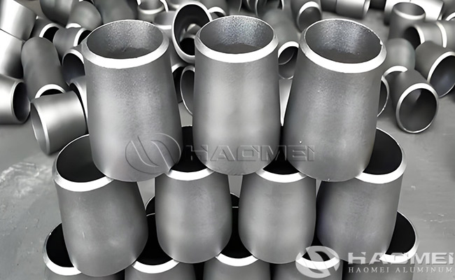
Types of Aluminum Reducer:
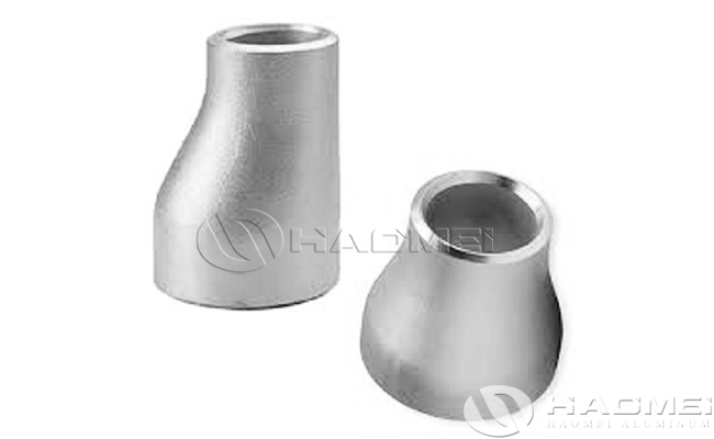
Aluminum reducer fittings can be divided into concentric and eccentric.
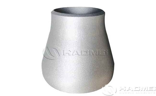
1. Concentric Reducer
Structural characteristics:
Geometric symmetry: the center axis of the pipes at both ends coincide, and the diameter changes along the axis of symmetrical transition (e.g. DN100 → DN80).
Smooth gradient: the bore is tapered, the angle is usually ≤ 30 °, to reduce turbulence and pressure drop.
Schematic diagram:

Big end (DN100) → tapering section → small end (DN80)
(centerline aligned, section shrinks uniformly)
Application Scenario:
Vertical piping: Fluid flow by gravity (e.g. high level tank outlet) to avoid fluid accumulation.
High flow rate system: need to reduce the pressure drop of the scene (such as ventilation ducts, cooling water circulation).
Symmetrical flow field requirements: laboratory equipment, precision instrument piping connections.
Advantages:
Low fluid resistance, low energy loss.
No restriction on installation direction, wide applicability.
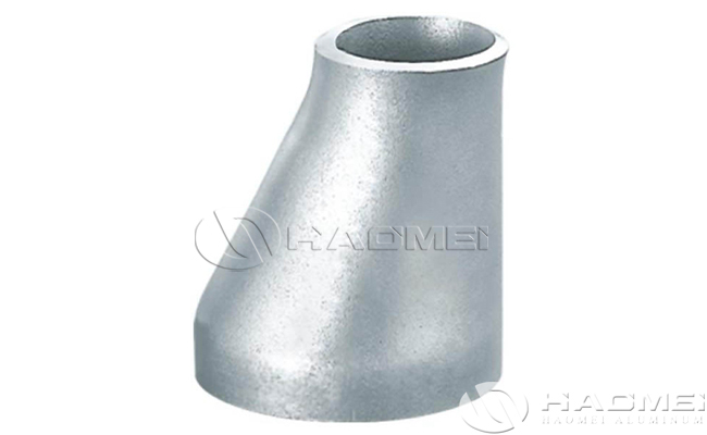
2. Eccentric Reducer
Structural characteristics:
Axis offset: the center axis of the big end and the small end are parallel but offset by a certain distance (usually offset = diameter difference / 2).
Flat bottom design: one side is kept flat and the other side is tilted and contracted (e.g. DN100→DN80).
Schematic diagram:

Big end (DN100) → offset tapering section → small end (DN80)
(Flat bottom side aligned, top side tilted and contracted)
Application Scenario:
Gas systems: Installation with flat bottom side up to prevent liquid stagnation (e.g. compressed air piping).
Liquid systems: Installation with flat bottom facing downwards to avoid gas stagnation (e.g. pump inlet).
Impurity-sensitive systems: sewage treatment, slurry transfer to minimize solids deposits.
Advantages:
Adapts to horizontal piping gas-liquid separation needs, reducing the risk of clogging.
Optimizes suction conditions for pumping equipment and prevents cavitation.
Concentric Reducer vs Eccentric Reducer
Characteristics | Concentric Reducing Fittings | Eccentric Reducing Fittings |
Structure | Symmetrical tapering, centerline coincidence | Asymmetric tapering, axial offset |
Mounting direction | Arbitrary Direction | Orientation by media type required (flat bottom facing up/down) |
Fluid Resistance | Low (low pressure drop) | Slightly higher (localized turbulence) |
Fluid/Gas Resistance | Not applicable to horizontal piping | Designed for horizontal piping |
Typical Industries | HVAC, vertical chemical piping | Petroleum, sewage, pumping stations |

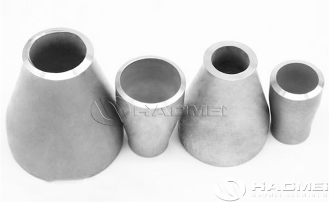
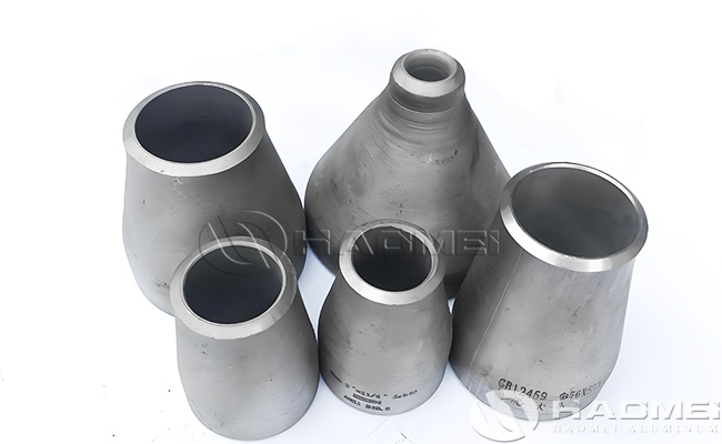
Available Sizes of Aluminium Reducers:
Aluminum reducer sizes are usually expressed in nominal diameters (DN) or inches (''). With 3 inches corresponding to DN80 (outside diameter of approximately 88.9mm) and 4 inches corresponding to DN100 (outside diameter of approximately 114.3mm).
Common combinations of reducers include:
3''→4'' (DN80→DN100): suitable for pipeline expansion needs, such as compressed air system or tanker unloading port.
4''→3'' (DN100→DN80): for reduction scenarios, commonly used in industrial equipment interface adaptation.
4'' to 3'' aluminum reducer | 4 inch to 3 inch aluminum reducer |
3'' to 4'' aluminum reducer | 3 inch to 4 inch aluminum reducer |
2.5'' to 3'' aluminum reducer | 2.5 inch to 3 inch aluminum reducer |
3.5'' to 3'' aluminum reducer | 3.5 inch to 3 inch aluminum reducer |
4'' to 3.5'' aluminum reducer | 4 inch to 3.5 inch aluminum reducer |
2'' to 2.5'' aluminum reducer | 2 inch to 2.5 inch aluminum reducer |
6'' to 4'' aluminum reducer | 6 inch to 4 inch aluminum reducer |
2'' to 2.5'' aluminum reducer | 2 inch to 2.5 inch aluminum reducer |
Available Types of Aluminum Reducer Fitting:
Butt Weld Pipe Reducers | Eccentric Reducers |
ASME B16.9 Butt weld Concentric Reducer | Concentric Reducers |
Reducer Pipe Fittings | Buttweld Concentric Reducer |
Aluminum Concentric Reducer | Buttweld Eccentric Reducer |
High Quality Concentric Reducer Manufacturer | Aluminum Eccentric Reducers |
Aluminum Reducer Suppliers | Eccentric Reducers Manufacturer |
High Quality Concentric Reducer | High Quality Eccentric Reducer |
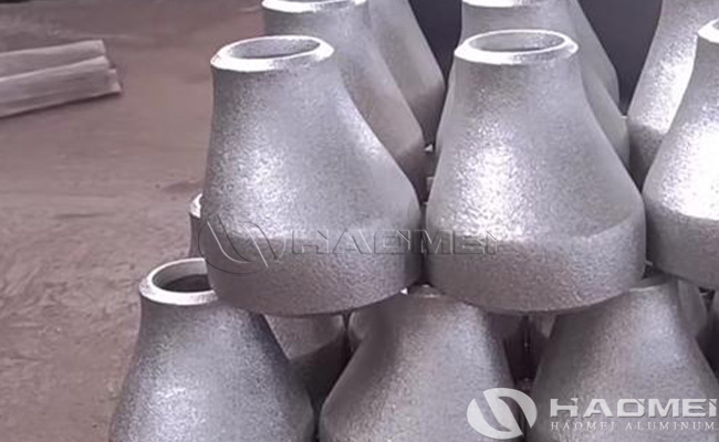
The Manufacturing Process of Aluminum Reducer:
1. Material selection: aluminum alloy (such as 6061, 7075) or special alloys (such as high-temperature resistant aluminum-silicon alloy).
2. Molding process:
Die-casting molding: suitable for complex structures (such as gas storage tank joints with reinforcement), machining threads and sealing surfaces after one-time molding.
Cold/Hot Processing: Adjust the tube diameter by cold drawing or hot extrusion to suit different size requirements.
3. Processing and treatment:
Stress relief treatment: Artificial aging or preheating after rough machining to reduce subsequent deformation (e.g. dimensional shrinkage during U-groove milling).
Surface treatment: anodized or sprayed to enhance corrosion resistance.
4. Welding and testing: TIG/MIG welding process is used to ensure the strength of the weld, and the sealing is verified by pressure test.
Aluminum Reducer Fittings Core Advantages:
1. Light weight and high strength to weight ratio
Aluminum alloy density is only 2.7g/cm³ (about 1/3 of steel), but through the alloy strengthening (such as 6061-T6, 7075) after the tensile strength of up to 300MPa or more.
2. Corrosion resistance and long life
Aluminum surface naturally generates dense alumina (Al₂O₃) film, which is resistant to atmospheric, fresh water and weak acid/alkali corrosion.
3. Fluid dynamics optimization
Diameter change design: Gradual shrinkage/expansion structure gently transitions to reduce turbulence and pressure drop (e.g. DN80→DN50 gradual shrinkage angle ≤15°).
Inner wall finish: Extrusion or polishing process to achieve Ra ≤ 0.8μm, reducing flow resistance.
4. Process flexibility and customization
Molding process:
Cold extrusion: suitable for small and medium diameter (DN15-DN100) precision reducer, size tolerance ± 0.1mm.
Die-casting molding: one-piece complex structure (such as gas storage tank joints with reinforcement), reducing welding points.
5. Thermal conductivity and electromagnetic compatibility
Thermal management advantages: thermal conductivity of 237W/(m-K), rapid temperature equalization to avoid local overheating (such as liquid-cooled server cooling circuit).
Non-magnetic interference: non-magnetic properties, suitable for MRI medical equipment, semiconductor cleanroom and other sensitive scenes.
6. Environmental protection and economy
Recyclable: Aluminum recycling consumes only 5% of the energy used in primary smelting, with a recycling rate of over 95%, in line with LEED green certification.
Cost-effective: Initial cost is higher than PVC but lower than stainless steel, with the lowest comprehensive life cycle cost.
Application of Aluminum Pipe Reducers:
Aluminum reducers are used in a wide range of applications, mainly in the following fields:
Plumbing and heating systems: used to connect water pipes of different sizes to ensure a smooth transition of water flow.
- Air conditioning and refrigeration systems: to connect pipes of different sizes and regulate refrigerant flow.
- Industrial piping: connecting pipes of different diameters to meet the needs of production processes.
- Automotive: for exhaust, cooling and fuel supply systems, adapting to different diameter connections.
- Aerospace: Widely used in hydraulic, fuel and pneumatic systems due to their lightweight and high strength characteristics.
- Chemical industry: used for the transportation of various chemicals with good corrosion resistance.
Power industry: connecting equipment such as boilers, steam turbines and cooling systems.


 |

Haomei Aluminum CO., LTD.

|

|
Company name: Haomei Aluminum CO., LTD.. Tel : +86-18137889531 Whatsapp : +86-18137889531 E-mail : nydia@aluminumhm.com


